The flow.cylc File Format
Aims
flow.cylc file format.A Cylc workflow is defined by a flow.cylc configuration
file, which uses a nested INI format:
flow.cylcfiles are divided into sections, written inside square brackets, i.e.[section-name].In this tutorial you will see
[scheduler]and[scheduling].Sections are nested by adding extra brackets:
[[sub-section]],[[[sub-sub-section]]], etc.Settings are written as
key = valuepairs within any section.Comments start with a
#character.
Note
Prior to Cylc 8, flow.cylc was named suite.rc,
but that name is now deprecated.
See Cylc 7 Compatibility Mode for information on compatibility with
existing Cylc 7 suite.rc files.
Example
# Comment
[section]
    key = value
    [[sub-section]]
        another-key = another-value  # Inline comment
        yet-another-key = """
            A
            Multi-line
            String
        """
Shorthand
In the documentation, we often use a compact single-line notation to refer to nested config items, where we drop the additional brackets at each level:
[section]An entire section.
[section]settingA setting within a section.
[section]setting=valueThe value of a setting within a section.
[section][sub section]another settingA setting within a sub-section.
This is purely for making it easier to refer to items; they cannot be written
this way in the flow.cylc file.
Duplicate Items
Duplicate sections get merged:
input
[a]
   c = C
[b]
   d = D
[a]  # duplicate
   e = E
|
result
[a]
   c = C
   e = E
[b]
   d = D
|
Duplicate settings get overwritten:
input
a = foo
a = bar  # duplicate
|
result
a = bar
|
Except for duplicate graph string items, which get merged:
input
R1 = "foo => bar"
R1 = "foo => baz"
|
result
R1 = "foo => bar & baz"
|
Indentation
It is a good idea to indent flow.cylc files for readability.
However, Cylc ignores indentation, so the following examples are equivalent:
input
[section]
    a = A
    [[sub-section]]
        b = B
    b = C
    # this setting is still
    # in [[sub-section]]
|
result
[section]
    a = A
    [[sub-section]]
        b = C
|
The Dependency Graph
Graph Strings
Cylc workflows are defined in terms of tasks and dependencies.
Task have names, and dependencies are represented by arrows
(=>) between them. For example, here’s a task make_dough that should
run after another task buy_ingredients has succeeded:
buy_ingredients => make_dough
These dependencies can be chained together in graph strings:
buy_ingredients => make_dough => bake_bread => sell_bread
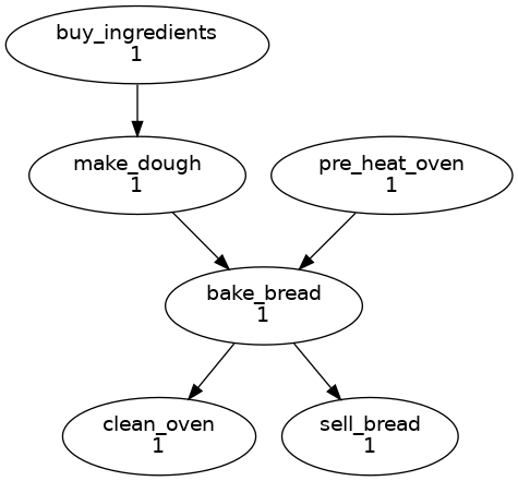
Graph strings can be combined to form more complex graphs:
buy_ingredients => make_dough => bake_bread => sell_bread
pre_heat_oven => bake_bread
bake_bread => clean_oven
Graphs can also contain logical operators & (and) and | (or).
For example, the following lines are equivalent to those just above:
buy_ingredients => make_dough
pre_heat_oven & make_dough => bake_bread => sell_bread & clean_oven
Collectively, all the graph strings make up the workflow dependency graph.
Note
The order of lines in the graph doesn’t matter, so the following examples are equivalent:
foo => bar
bar => baz
|
bar => baz
foo => bar
|
Cylc Graphs
A non-cycling graph can be defined with [scheduling][graph]R1,
where R1 means run once:
[scheduling]
    [[graph]]
        R1 = """
            buy_ingredients => make_dough
            pre_heat_oven & make_dough => bake_bread
            bake_bread => sell_bread & clean_oven
        """
This is a minimal Cylc workflow that defines a graph of tasks to run, but does not yet say what scripts or applications to run for each task. We will cover that later in the runtime tutorial.
Cylc provides a command line utility
for visualising graphs, cylc graph <path>, where
path is the location of the flow.cylc file.
It generates diagrams similar to the ones you have seen so far. The number
1 below each task is the cycle point. We will explain what this
means in the next section.
Hint
A graph can be drawn in multiple ways, for instance the following two examples are equivalent:

Graphs drawn by cylc graph may vary slightly from one run to
another, but the tasks and dependencies will always be the same.
Practical
In this practical we will create a new Cylc workflow and write a graph of tasks for it to run.
Create a Cylc workflow.
A Cylc workflow is defined by a
flow.cylcfile.If you don’t have one already, create a
cylc-srcdirectory in your user space:mkdir ~/cylc-src
Now create a new workflow source directory called
graph-introductionundercylc-srcand move into it:mkdir ~/cylc-src/graph-introduction cd ~/cylc-src/graph-introduction
In your new source directory create a
flow.cylcfile and paste the following text into it:[scheduler] allow implicit tasks = True [scheduling] [[graph]] R1 = """ # Write graph strings here! """
Write a graph.
We now have a blank Cylc workflow. Next we need to define a graph.
Edit your
flow.cylcfile to add graph strings representing the following graph:Visualise the workflow.
Once you have written some graph strings try using
cylc graphto display the workflow. Run the following command:cylc graph .
Note
cylc graphtakes the path to the workflow as an argument. Inside the source directory we can just runcylc graph ..If the results don’t match the diagram above try to correct the graph in your
flow.cylcfile.Solution
There are multiple correct ways to write this graph. So long as what you see from
cylc graphmatches the above diagram then you have a correct solution.Two valid examples:
a & c => b => d & f
d => e
a => b => d => e
c => b => f
The whole workflow should look something like this:
[scheduler]
    allow implicit tasks = True
[scheduling]
    [[graph]]
        R1 = """
            a & c => b => d & f
            d => e
        """