Scheduling Configuration
Related Tutorial
The [scheduling] section of the flow.cylc file
defines what tasks exist in the workflow, in a dependency graph,
and when they should run, relative to each other and to constraints such as
clock triggers, external triggers, and internal queues
The Graph
Related Tutorial
The graph defines a workflow in terms of its tasks and the dependencies between them.
A Cylc graph is composed of one or more graph strings which use a special syntax to define the dependencies between tasks:
arrow symbols
=>declare dependencieslogical operators
&(AND) and|(OR) can be used to write conditional dependencies.
The left side of a dependency arrow shows a logical combination of one or more task outputs. The right side shows which tasks to trigger when those outputs are complete:
For example:
# if foo AND bar succeed, run baz
foo:succeeded & bar:succeeded => baz
However, :succeeded is so often required that it is automatically added to plain
task names on the left side of dependencies, as a convenience:
# short for "foo:succeeded & bar:succeeded => baz"
foo & bar => baz
See also
Task outputs in dependency expressions also determine whether the outputs are “required” (by default) or “optional” (with a ‘?’ appended) - see Required and Optional Outputs.
Graph strings are configured under the [scheduling][graph] section
of the flow.cylc file:
[scheduling]
    [[graph]]
        R1 = """
            foo & bar => baz
        """
In this example R1 is a recurrence expression that
defines how often, and on what cycle interval, to run this part of the graph.
For example, R1 means run once, and P1D means run repeatedly on a 1-day
cycle.
Graph strings may contain blank lines, arbitrary white space and comments e.g:
[scheduling]
    [[graph]]
        R1 = """
            foo & bar => baz  # baz depends on foo and bar

        """
Graphs can be broken down into pairs of triggers, where the left side is a single task output, or a logical expression involving several of them, and the right side is the task or family that triggers when the output (or expression) is completed.
In the case of cycling tasks, triggers are valid for cycle points matching the recurrence expression for the graph string. For example this graph:
[scheduling]
    [[graph]]
        T00,T12 = "A => B"
implies that B triggers off of A (i.e. off of the A:succeeded output)
for cycle points where the hour matches 00 or 12. To define intercycle
dependencies, attach an offset indicator to the left side of a pair:
[scheduling]
    [[graph]]
        T00,T12 = "A[-PT12H] => B"
This means task B triggers off of task A[-PT12H] (12 hours before, with
respect to cycle point) at every point with hours matching 00 and 12 in
a sequence starting at the initial cycle point.
Note: current cycle point is implicit - only offsets need to be specified -
because most tasks depend only on others with the same cycle point.
Cycle point offsets can only appear on the left side of an arrow. However,
A => B[-PT6H], which is illegal, can be reformulated as a future
trigger A[+PT6H] => B (see Intercycle Triggers). It is also
possible to combine multiple offsets within a cycle point offset e.g.
[scheduling]
    [[graph]]
        T00,T12 = "A[-P1D-PT12H] => B"
This means that B triggers off A[-P1D-PT12H] (1 day and 12 hours before)
at each cycle point.
Triggers can be chained together. This graph:
T00, T12 = """
    A => B  # B triggers off A
    B => C  # C triggers off B
"""
is equivalent to this:
T00, T12 = "A => B => C"
All triggers defined for the same task combine, so this:
T00, T12 = """
    A => X  # X triggers off A
    B => X  # X also triggers off B
"""
is equivalent to this:
T00, T12 = "A & B => X" # X triggers off A AND B
In summary, the branching tree structure of a dependency graph can
be partitioned into lines (in the flow.cylc graph string) of
dependency pairs or chains, in any way you like. Use white space and comments
to make the graph as clear as possible.
# B triggers if A succeeds, then C and D trigger if B succeeds:
R1 = "A => B => C & D"

# which is equivalent to this:
R1 = """
    A => B => C
    B => D
"""

# and to this:
R1 = """
    A => B => D
    B => C
"""

# and to this:
R1 = """
    A => B
    B => C
    B => D
"""

# and it can even be written like this:
R1 = """
    A => B # blank line follows:

    B => C # comment ...
    B => D
"""
Splitting Up Long Graph Lines
It is not necessary to use the fragile line continuation marker \ to split
long graph lines. You can break at dependency arrows (=>) and operators
(&, |), or split long chains into smaller ones. This graph:
R1 = "A & B => C"
is equivalent to this:
R1 = """
    A & B =>
    C
"""
and also to this:
R1 = """
    A &
    B => C
"""
Note
Multiple graph strings add together to make the complete workflow graph.
Changed in version 8.0.0: Graph strings can be broken on & and | as well as =>.
Graph Types
Non-Cycling
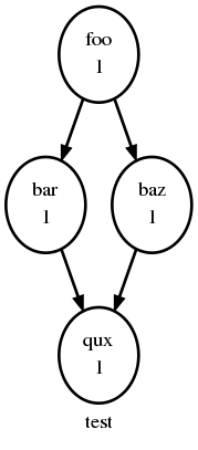
The following is a small workflow of non-cycling tasks; these all have a
single cycle point (1), and once they’re all finished the scheduler
shuts down.
[scheduling]
    [[graph]]
        R1 = "foo => bar & baz => qux"
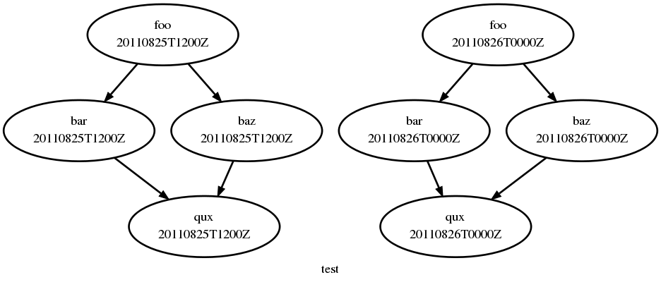
Cycling Graphs
For cycling tasks we give a recurrence expression that defines a sequence of cycle points for which the graph string is valid, as demonstrated here for a small workflow of cycling tasks:
[scheduling]
    [[graph]]
       # (note no dependence between cycle points)
        T00,T12 = "foo => bar & baz => qux"
Related Tutorial
For example in the following scenario:
[scheduling]
    [[graph]]
        T06 = foo => bar
T06 means “Run every day starting at 06:00 after the
initial cycle point”. Cylc allows you to start (or end) at any particular
time, repeat at whatever frequency you like, and even optionally limit the
number of repetitions.
Cycling Syntax Rules
Datetime cycling information is made up of:
a datetime that typically specifies the start point of the sequence
an interval between points in the sequence
and an optional limit on the number of points in the sequence
The time is assumed to be in UTC unless you set
[scheduler]cycle point time zone.
Attention
Changed in version 8.0.0.
At Cylc 7 the time zone was assumed to be local time unless
[scheduler]cycle point time zone or [scheduler]UTC mode
was set. If your workflow is running in
Cylc 7 compatibility mode
this remains the case.
The calendar is assumed to be the proleptic Gregorian calendar unless
you set [scheduling]cycling mode.
The syntax is based on the ISO 8601 datetime standard, which includes the representation of datetimes and intervals. Cylc (optionally) allows these representations to be heavily condensed by omitting information that can be inferred from context (rules below).
Important
Cycle points in Cylc are just task labels that anchor dependence on other tasks, and which tasks can use to determine their current cycle point. Datetime cycle points have no relation to wallclock (real) time except where specific tasks, if any, depend on clock triggers.
There are three ISO 8601 recurrence formats supported by Cylc, detailed below in order from most commonly used to least commonly used.
Format 3: R[limit?]/[datetime]/[interval]
The most common full form for recurrences is
R[limit?]/[datetime]/[interval]. This is format number 3 in the ISO 8601
standard. The datetime specifies the start of the cycling sequence.
For example, R3/2000-01-01T00Z/P2D means “run 3 times, every 2 days,
starting at 2000-01-01T00Z (midnight, Jan 1st 2000)”; the list of points
on this sequence is:
2000-01-01T00Z
2000-01-03T00Z
2000-01-05T00Z
In Cylc, this form can be condensed to:
R[limit?]/[datetime]
R[limit?]//[interval]
[datetime]/[interval]
R[limit?] # Special limit of 1 case
[datetime]
[interval]
Here are some examples for each form:
R5/T00            # Run 5 times at 00:00 every day
R//PT1H           # Run every hour (Note the R// is optional)
20000101T06Z/P1D  # Run every day starting at 06:00 1st Jan 2000
R1                # Run once at the initial cycle point
R1/20000101T00Z   # Run once at 00:00 1st Jan 2000
P1Y               # Run every year
Note
T00 is an example of [datetime], with an
inferred 1 day period and no limit (it is short for R/T00).
Where some or all datetime information is omitted, it is inferred to
be relative to the initial cycle point. For example, T00
by itself would mean the next occurrence of midnight that follows, or is, the
initial cycle point. +PT6H means 6 hours after the initial cycle point.
-P1D means 1 day before the initial cycle point. The default is the initial
cycle point itself.
If the interval is omitted and some (but not all) datetime information is
omitted, it is inferred to be a single unit above the largest given specific
datetime unit. For example, the largest given specific unit in T00 is
hours, so the inferred interval is 1 day (daily), P1D.
If the limit is omitted, unlimited cycling is assumed. This will be bounded by the workflow’s final cycle point if given.
Format 4: R[limit?]/[interval]/[datetime]
Another supported recurrence form is:
R[limit?]/[interval]/[datetime] (format number 4 in the ISO 8601 standard).
This uses the datetime as the end of the cycling sequence rather than the start.
For example, R3/P5D/2014-04-30T06 means “run 3 times, every 5 days, ending
at 2014-04-30T06 (06:00, April 30th 2014)”; the list of points on this
sequence is:
2014-04-20T06
2014-04-25T06
2014-04-30T06
This form can be used to get special behaviour relative to the final cycle point.
We can also represent this in Cylc with a collapsed form:
R[limit?]/[interval]
R[limit?]//[datetime]
[interval]/[datetime]
So, for example, you can write:
R1//+P0D  # Run once at the final cycle point
R5/P2D    # Run 5 times, every 2 days, ending at the final cycle point
P2W/T00   # Run every 2 weeks ending at 00:00 before/at the final cycle point
R//T00    # Run every day ending at 00:00 before/at the final cycle point
Format 1: R[limit?]/[datetime]/[datetime]
A less common recurrence form is R[limit?]/[datetime]/[datetime]
(format number 1 in the ISO 8601 standard). This uses the difference between
the first datetime and the second datetime to set the recurrence interval.
The first datetime is the start point. For example,
R3/2020-07-10/2020-07-15 means “run 3 times, every 5 days, starting at
2020-07-10 (midnight, July 10th 2020)”; the list of points on this sequence is:
2020-07-10
2020-07-15
2020-07-20
Caution
Cylc will always calculate the interval in
exact datetime units. So for the example
of R/2004/2005, the interval will be P366D (2004 is a leap year)
rather then P1Y, because year is an
inexact unit.
Note
In versions of Cylc prior to 8.0.0, this syntax was undocumented and behaved differently, in a way which was not in accordance with the ISO 8601 standard.
Referencing The Initial And Final Cycle Points
The caret and dollar symbols are shorthand for the initial and final cycle points:
R1/^+PT12H  # Repeat once 12 hours after the initial cycle point
            # R[limit]/[datetime]
            # Equivalent to R1/+PT12H
R1/$        # Repeat once at the final cycle point
            # R[limit]/[datetime]
            # Equivalent to R1//+P0D
$-P2D/PT3H  # Repeat 3 hourly starting two days before the
            # [datetime]/[interval]
            # final cycle point
Note
There are multiple ways to write the same recurrences, for instance the following all run once at the final cycle point:
R1/P0Y       # R[limit]/[interval]
R1/P0Y/$     # R[limit]/[interval]/[datetime]
R1/$         # R[limit]/[datetime]
The Initial Cycle Point
A workflow normally begins running at the initial cycle point, which defines the start of the workflow graph:
[scheduling]
    initial cycle point = 20100808T06Z
This can be overridden on the command line:
$ cylc play foo --initial-cycle-point=20120808T06Z
Setting The Initial Cycle Point Relative To The Current Time
Warning
Setting the initial cycle point relative to the current time only works for datetime cycling workflows using the Gregorian calendar. It does not work for alternative calendars like the 360, 365 or 366 day calendars, or integer cycling.
The next and previous syntax can be used with truncated ISO 8601
representations, to set the initial cycle point:
next(Thh:mmZ), previous(T-mm); e.g.
initial cycle point = next(T15:00Z)initial cycle point = previous(T09:00)initial cycle point = next(T12)initial cycle point = previous(T-20)
A list of times, separated by semicolons, can be provided, e.g.
next(T-00;T-15;T-30;T-45). At least one time is required within the
brackets, and if more than one is given, the major time unit in each (hours
or minutes) should be of the same type.
Note
T-00 means every hour, on the hour. The - is a placeholder for the hours column.
If an offset from the specified datetime is required, this should be
of the form previous(Thh:mm) +/- PxTy as is used
for determining cycle periods, e.g.
initial cycle point = previous(T06) +P1Dinitial cycle point = next(T-30) -PT1H
The next/previous syntax is interpreted first, then the offset is applied.
Offsets used without next or previous are interpreted as offsets from “now”.
Syntax |
Interpretation |
|---|---|
|
2018-03-14T16:00Z |
|
2018-03-14T15:00Z |
|
2018-03-14T15:15Z |
|
2018-03-14T15:00Z |
|
2018-03-15T00:00Z |
|
2018-03-14T00:00Z |
|
2018-03-15T06:30Z |
|
2018-03-13T06:30Z |
|
2018-03-14T18:00Z |
|
2018-03-14T12:00Z |
|
2018-03-21T18:00Z |
|
2018-03-14T16:12Z |
|
2018-02-14T15:12Z |
Relative initial cycle points also work with truncated dates, including weeks and ordinal date, using ISO 8601 truncated date representations. Note that day-of-week should always be specified when using weeks. If a time is not included, the calculation of the next or previous corresponding point will be done from midnight of the current day.
Syntax |
Description |
Interpretation |
|
Any century; next year 00 |
2100-01-01 |
|
Any year; next month 01 |
2018-01-01 |
|
Any year; any month; next 1st of month |
2018-04-01 |
|
Any year; previous Dec 25 |
2017-12-25 |
|
Any century; next June in a year ending 20 |
2020-06-01 |
|
Any century; previous week 10 day 1 |
2018-03-05 |
|
Any year; any week; next day 1, 3 or 5 |
2018-03-14 |
|
Any year; day 1, 91, 181 or 271 |
2018-04-01 |
|
Any year; previous day 356 at 12Z |
2017-12-31T12:00Z |
The Environment Variable CYLC_WORKFLOW_INITIAL_CYCLE_POINT
At start up the initial cycle point is passed to job environments
as $CYLC_WORKFLOW_INITIAL_CYCLE_POINT and stored in the workflow
database to persist across restarts.
The $CYLC_WORKFLOW_INITIAL_CYCLE_POINT variable allows tasks to
check if they are running in the initial cycle point, when different behaviour
may be required. Note however that an initial R1 graph section is the
preferred way to get different behaviour at workflow start-up.
How Multiple Graph Strings Combine
Multiple graph strings add together to make the complete workflow graph. Recurrences can overlap, and tasks can appear in multiple graph strings. It is OK (but unnecessary) to define duplicate dependencies.
[scheduling]
    [[graph]]
        T00,T06,T12,T18 = "A => B => C"
        T06,T18 = "B => C => X"
        # duplicate prerequisite: B => C already defined at T06, T18
This graph can be written more concisely, with the same result, like this:
[scheduling]
    [[graph]]
        T00,T06,T12,T18 = "A => B => C"
        # X triggers off C only at 6 and 18 hours
        T06,T18 = "C => X"
Exclusions
Exclusions allow you to subtract dates or recurrences from a cycling section using the exclamation mark symbol (!).
Excluding Dates
datetimes can be excluded from a recurrence
by an exclamation mark for example PT1D!20000101 means run daily except on
the first of January 2000.
This syntax can be used to exclude multiple datetimes from a recurrence, using
the syntax PT1D!(20000101,20000102,...). All datetimes listed within
the parentheses will be excluded.
Note
The ^ and $ symbols (shorthand for the initial
and final cycle points) are both datetimes so T12!$-PT1D
is valid.
If using a run limit in combination with an exclusion, the recurrence might not
run the expected number of times. For example, in the following
workflow foo will only run once as its second run is excluded.
[scheduling]
    initial cycle point = 20000101T00Z
    final cycle point = 20000105T00Z
    [[graph]]
        R2/P1D!20000102 = foo
Excluding Recurrences
Exclusions may themselves be datetime recurrence sequences. Any partial datetime or sequence after the exclamation mark will be excluded from the main sequence.
For example, partial datetimes can be excluded like this:
PT1H ! T12                   # Run hourly but not at 12:00 from the initial
                             # cycle point.
T-00 ! (T00, T06, T12, T18)  # Run hourly but not at 00:00, 06:00,
                             # 12:00, 18:00.
PT5M ! T-15                  # Run 5-minutely but not at 15 minutes past the
                             # hour from the initial cycle point.
T00 ! W-1T00                 # Run daily at 00:00 except on Mondays.
And sequences can be excluded like this:
PT1H ! PT6H         # Run hourly from the initial cycle point but
                    # not 6-hourly from the initial cycle point.
T-00 ! PT6H         # Run hourly on the hour but not 6-hourly on the hour.
# Same as T-00 ! T-00/PT6H (T-00 context is implied)
# Same as T-00 ! (T00, T06, T12, T18)
# Same as PT1H ! (T00, T06, T12, T18) Initial cycle point dependent

T12 ! T12/P15D      # Run daily at 12:00 except every 15th day.

R/^/P1H ! R5/20000101T00/P1D    # Any valid recurrence may be used to
                                # determine exclusions. This example
                                # means: Repeat every hour from
                                # the initial cycle point, but exclude
                                # 00:00 for 5 days from 1 January 2000.
You can combine exclusion sequences and single point exclusions like this:
T-00 ! (20000101T07, PT2H)  # Run hourly on the hour but not at 07:00
                            # on the 1st Jan, 2000 and not 2-hourly
                            # on the hour.
Advanced Examples
Here are several examples of Cylc graph recurrence expressions:
R1         # Run once at the initial cycle point
P1D        # Run every day starting at the initial cycle point
PT5M       # Run every 5 minutes starting at the initial cycle point
T00/P2W    # Run every 2 weeks starting at 00:00 after the
           # initial cycle point
+P5D/P1M   # Run every month, starting 5 days after the initial cycle point
R1/T06     # Run once at 06:00 after the initial cycle point
R1/P0Y     # Run once at the final cycle point
R1/$       # Run once at the final cycle point (alternative form)
R1/$-P3D   # Run once three days before the final cycle point
R3/T0830   # Run 3 times, every day at 08:30 after the initial cycle point
R3/01T00   # Run 3 times, every month at 00:00 on the first
           # of the month after the initial cycle point
R5/W-1/P1M # Run 5 times, every month starting on Monday
           # following the initial cycle point
T00!^      # Run at the first occurrence of T00 that isn't the
           # initial cycle point
PT1D!20000101  # Run every day days excluding 1st Jan 2000
20140201T06/P1D    # Run every day starting at 20140201T06
R1/min(T00,T06,T12,T18)  # Run once at the first instance
                         # of either T00, T06, T12 or T18
                         # starting at the initial cycle point
Advanced Starting Up
Dependencies that are only valid at the initial cycle point can be
written using an R1 recurrence. For example:
[scheduling]
    initial cycle point = 20130808T00
    final cycle point = 20130812T00
    [[graph]]
        R1 = "prep => foo"
        T00 = "foo[-P1D] => foo => bar"
In the example above, R1 implies R1/20130808T00, so
prep only runs once at that cycle point (the initial cycle point).
foo will depend on prep there, but not at subsequent cycle points.
However, it is possible to have a workflow that has multiple effective initial
cycles - for example, one starting at T00 and another starting
at T12. What if they need to share an initial task?
Let’s suppose that we add the following section to the workflow example above:
[scheduling]
    initial cycle point = 20130808T00
    final cycle point = 20130812T00
    [[graph]]
        R1 = "prep => foo"
        T00 = "foo[-P1D] => foo => bar"
        T12 = "baz[-P1D] => baz => qux"
We’ll also say that there should be a starting dependence between
prep and our new task baz - but we still want to have
a single prep task, at a single cycle.
We can write this using a special case of the task[-interval] syntax -
if the interval is null, this implies the task at the initial cycle point.
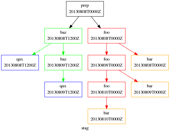
For example, we can write our workflow like so, to produce the graph as shown:
Staggered Start Workflow
[scheduling]
    initial cycle point = 20130808T00
    final cycle point = 20130812T00
    [[graph]]
        R1 = "prep"
        # ^ implies the initial cycle point:
        R1/T00 = "prep[^] => foo"
        # ^ is initial cycle point, as above:
        R1/T12 = "prep[^] => baz"
        T00 = "foo[-P1D] => foo => bar"
        T12 = "baz[-P1D] => baz => qux"
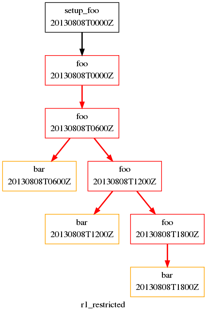
Usually, we want to specify additional tasks and dependencies at the initial cycle point. But what if we want our first cycle point to be entirely special, with some tasks missing compared to subsequent cycle points?
In the workflow below, bar will not run at the initial cycle point, but
will still run at subsequent cycle points. +PT6H/PT6H means start at
+PT6H (6 hours after the initial cycle point) and then repeat every
PT6H (6 hours):
Restricted First Cycle Point Workflow
[scheduling]
    initial cycle point = 20130808T00
    final cycle point = 20130808T18
    [[graph]]
        R1 = "setup_foo => foo"
        +PT6H/PT6H = """
            foo[-PT6H] => foo
            foo => bar
        """
Some workflows may have staggered start-up sequences where different tasks need
to run once but only at specific cycle points, e.g. because of differing
data sources at different cycle points, with different possible initial cycle
points. To allow this Cylc provides a min( ) function that can be
used as follows:
[scheduling]
    initial cycle point = 20100101T03
    [[graph]]
        R1/min(T00,T12) = "prep1 => foo"
        R1/min(T06,T18) = "prep2 => foo"
        T00,T06,T12,T18 = "foo => bar"
In this example the initial cycle point is 20100101T03, so the
prep1 task will run once at 20100101T12 and the
prep2 task will run once at 20100101T06 as these are
the first cycle points after the initial cycle point in the respective
min( ) entries.
Integer Cycling
Related Tutorial
In addition to non-cycling and datetime cycling workflows, Cylc can do integer cycling for cycling workflows that are not datetime based.
To construct an integer cycling workflow, set
[scheduling]cycling mode=integer, and specify integer values
for the initial cycle point and optionally the
final cycle point. The syntax for intervals,
offsets, and recurrences (sequences) is similar to the
datetime cycling syntax, except for the simple integer values.
The full integer recurrence expressions supported are:
Rn/start-point/interval # e.g. R3/1/P2Rn/interval/end-point # e.g. R3/P2/9
But, as for datetime cycling, sequence start and end points can be omitted where workflow initial and final cycle points can be assumed. Some examples:
R1        # Run once at the initial cycle point
          # (short for R1/initial-point/?)
P1        # Repeat with step 1 from the initial cycle point
          # (short for R/initial-point/P1)
P5        # Repeat with step 5 from the initial cycle point
          # (short for R/initial-point/P5)
R2//P2    # Run twice with step 3 from the initial cycle point
          # (short for R2/initial-point/P2)
R/+P1/P2  # Repeat with step 2, from 1 after the initial cycle point
R2/P2     # Run twice with step 2, to the final cycle point
          # (short for R2/P2/final-point)
R1/P0     # Run once at the final cycle point
          # (short for R1/P0/final-point)
Advanced Integer Cycling Syntax
The same syntax used to reference the initial and final cycle points (introduced in Referencing The Initial And Final Cycle Points) for use with datetime cycling can also be used for integer cycling. For example you can write:
R1/^     # Run once at the initial cycle point
R1/$     # Run once at the final cycle point
R3/^/P2  # Run three times with step two starting at the
                 # initial cycle point
Likewise the syntax introduced in The Initial Cycle Point for excluding a particular point from a recurrence also works for integer cycling. For example:
R/P4!8       # Run with step 4, to the final cycle point but not at point 8
R3/3/P2!5    # Run with step 2 from point 3 but not at point 5
R/+P1/P6!14  # Run with step 6 from 1 step after the
             # initial cycle point but not at point 14
Multiple integer exclusions are also valid in the same way as the syntax in The Initial Cycle Point. Integer exclusions may be a list of single integer points, an integer sequence, or a combination of both:
R/P1!(2,3,7)  # Run with step 1 to the final cycle point,
              # but not at points 2, 3, or 7.
P1 ! P2       # Run with step 1 from the initial to final
              # cycle point, skipping every other step from
              # the initial cycle point.
P1 ! +P1/P2   # Run with step 1 from the initial cycle point,
              # excluding every other step beginning one step
              # after the initial cycle point.
P1 !(P2,6,8)  # Run with step 1 from the initial cycle point,
              # excluding every other step, and also excluding
              # steps 6 and 8.
An Integer Cycling Example
The following workflow definition, as graphed above, implements a classical linear pipeline using integer cycling. The workflow ensures that one instance each of A, B, and C runs concurrently and the pipeline is kept full: when 1/A has finished processing the first dataset, 2/A can start on the second one at the same time as 1/B begins processing the output of 1/A, and so on. The artificial cross-cycle dependence ensures that only one instance of A can run at a time; and similarly B and C. If available compute resource supports more than three concurrent jobs, remove the cross-cycle dependence and Cylc will run many cycles at once. Task runtime configuration is omitted, but it would likely involve retrieving datasets by cycle point and processing them in cycle point-specific shared workspaces under the self-contained run directory.
[scheduling]
    cycling mode = integer
    initial cycle point = 1
    [[graph]]
        R/^/P1 = """
            A => B => C
            A[-P1] => A
            B[-P1] => B
            C[-P1] => C
        """
Task Triggering
A task is said to trigger when it submits its job to run, as soon as all of
its dependencies (also known as its separate “triggers”) are met. Tasks can
be made to trigger off of the state of other tasks (indicated by a
:state qualifier on the upstream task (or family)
name in the graph) and, and off the clock, and arbitrary external events.
External triggering is relatively more complicated, and is documented separately in External Triggers.
Success Triggers
The default, with no trigger type specified, is to trigger off of the upstream task succeeding:
# B triggers if A SUCCEEDS:
R1 = "A => B"
For consistency and completeness, however, the success trigger can be explicit:
# B triggers if A SUCCEEDS:
R1 = "A => B"

# or:
R1 = "A:succeed => B"
Failure Triggers
To trigger off of the upstream task failing:
# B triggers if A FAILS:
R1 = "A:fail => B"
Start Triggers
To trigger off of the upstream task starting:
# B triggers if A STARTS EXECUTING:
R1 = "A:start => B"
This can be used to trigger tasks that monitor the execution of other tasks, e.g. to process their output files on the fly as they are generated. Message Triggers can also be useful for this use case.
Finish Triggers
To trigger off of the upstream task either succeeding or failing:
# B triggers if A either SUCCEEDS or FAILS:
R1 = "A | A:fail => B"

# or
R1 = "A:finish => B"
Message Triggers
Related Tutorial
We can also trigger off of custom task output messages. These must be
registered in the [runtime][<namespace>][outputs] section
of the emitting task, and sent with cylc message command.
The graph trigger syntax refers to the item name of the registered
output message. Here’s an example workflow that uses message triggers:
[scheduling]
    initial cycle point = 20140801T00
    final cycle point = 20141201T00
    [[graph]]
        P2M = """
            foo:out1 => bar
            foo[-P2M]:out2 => baz
        """
[runtime]
    [[foo]]
        script = """
            sleep 5
            cylc message -- "${CYLC_WORKFLOW_ID}" "${CYLC_TASK_JOB}" "file 1 done"
            sleep 10
            cylc message -- "${CYLC_WORKFLOW_ID}" "${CYLC_TASK_JOB}" "file 2 done"
            sleep 10
        """
        [[[outputs]]]
            out1 = "file 1 done"
            out2 = "file 2 done"
    [[bar, baz]]
        script = sleep 10
Job Submission Triggers
To trigger off of a task submitting, or failing to submit:
# B triggers if A submits successfully:
R1 = "A:submit? => B"

# D triggers if C fails to submit successfully:
R1 = "C:submit-fail? => D"
A possible use case for submit-fail triggering: if a task fails to submit, possibly after multiple retries, another task that inherits (mostly) the same runtime could be triggered to submit the same job to an alternative platform.
Conditional Triggers
Conditional triggers allow the configuration of more advanced task dependencies.
AND operators (&) can appear on both sides of an arrow. They
provide a concise alternative to defining multiple triggers separately:
# 1/ this:
R1 = "A & B => C"

# is equivalent to:
R1 = """
    A => C
    B => C
"""

# 2/ this:
R1 = "A => B & C"

# is equivalent to:
R1 = """
    A => B
    A => C
"""

# 3/ and this:
R1 = "A & B => C & D"

# is equivalent to this:
R1 = """
    A => C
    B => C
    A => D
    B => D
"""
OR operators (|), for conditional triggers, can only appear on the left:
# C triggers when either A or B finishes:
    R1 = "A | B => C"
Any valid conditional expression can be used.
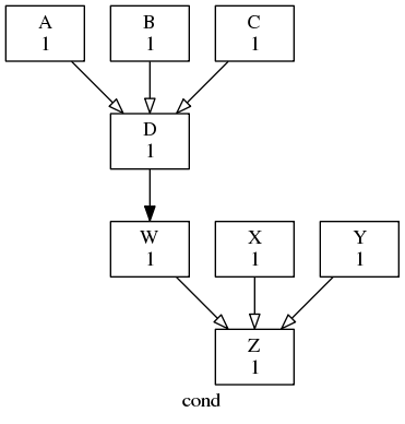
Conditional trigger example
# D triggers if A or (B and C) succeed
A | B & C => D
# just to align the two graph sections
D => W
# Z triggers if (W or X) and Y succeed
(W|X) & Y => Z
Family Triggers
Families defined by the runtime inheritance hierarchy (Task Configuration) can be used in the graph to trigger whole groups of tasks at the same time (e.g. forecast model ensembles and groups of tasks for processing different observation types at the same time) and for triggering downstream tasks off families as a whole. Higher level families, i.e. families of families, can also be used, and are reduced to the lowest level member tasks.
Note
Tasks can also trigger off individual family members if necessary.
To trigger an entire task family at once:
[scheduling]
    [[graph]]
        R1 = "foo => FAM"
[runtime]
    [[FAM]]    # a family (because others inherit from it)
    [[m1,m2]]  # family members (inherit from FAM)
        inherit = FAM
This is equivalent to:
[scheduling]
    [[graph]]
        R1 = "foo => m1 & m2"
[runtime]
    [[FAM]]
    [[m1,m2]]
        inherit = FAM
To trigger off of a task family you must specify whether the trigger condition applies to all or any of the member tasks:
[scheduling]
    [[graph]]
        R1 = """
            # all-member triggers:
            FAM:start-all => one
            FAM:succeed-all => one
            FAM:fail-all => one
            FAM:finish-all => one
            # any-member triggers:
            FAM:start-any => one
            FAM:succeed-any => one
            FAM:fail-any => one
            FAM:finish-any => one
        """
Here’s how to trigger downstream processing after if one or more family members succeed, but only after all members have finished (succeeded or failed):
[scheduling]
    [[graph]]
        R1 = """
           FAM:finish-all & FAM:succeed-any => foo
        """
Efficient Inter-Family Triggering
While Cylc allows writing dependencies between two
families it is important to consider the number of
dependencies this will generate. In the following example, each member of
FAM2 has dependencies pointing at all the members of FAM1.
[scheduling]
    [[graph]]
        R1 = """
            FAM1:succeed-any => FAM2
        """
Expanding this out, you generate N * M dependencies, where N is the
number of members of FAM1 and M is the number of members of FAM2.
This can result in high memory use as the number of family members grows.
You can greatly reduce the number of dependencies generated here by putting
dummy tasks in the graph to represent the state of the
upstream family. For example, if FAM2 should trigger off any member of
FAM1 succeeding you can use a dummy tasks
FAM1_done like this:
[scheduling]
    [[graph]]
        R1 = """
            FAM1:succeed-any => FAM1_done => FAM2
        """
[runtime]
# ...
    [[FAM1_done]]
        run mode = skip
# ...
This graph generates only N + M dependencies, which takes
significantly less memory and CPU to store and evaluate.
Note
By setting [runtime][<namespace>]run mode to skip,
the task will instantly complete without submitting a job.
See Skip Mode.
Intercycle Triggers
Most tasks in a workflow typically depend on others with the same cycle point, but some may depend on other cycle points [1].
Intercycle dependence is expressed using
[offset] syntax such as foo[-PT12H] => foo, which means foo at the
current cycle point depends on a previous instance of foo at 12 hours
before the current cycle point. Unlike for recurrences (e.g. T00,T12),
dependency these offsets are relative to the current cycle point, not the
initial cycle point.
[[graph]]
    # B triggers off A in the previous cycle point
    PT6H = "A[-PT6H] => B"
intercycle and trigger type (or message trigger) syntax can be combined:
# B triggers if A in the previous cycle point fails:
PT6H = "A[-PT6H]:fail => B"
For convenience, Cylc automatically ignores intercycle triggers that reach back
beyond the initial cycle point. If something special has to happen at start-up,
R1 tasks are the recommended way to make it happen:
[scheduling]
    [[graph]]
        R1 = "prep1 => prep2"
        R1/T00,R1/T12 = "prep2[^] => foo"
        T00,T12 = "foo[-PT12H] => foo => bar"
Here there is a dependence on the initial R1 task prep for foo at
the first T00 cycle point, and at the first T12 cycle point.
Thereafter, foo just depends on its previous (12 hours ago) instance.
It can also be useful to have specific dependencies on tasks at or near
the initial cycle point. You can switch the context of the offset to be
the initial cycle point by using the caret symbol: ^.
For example, foo[^] means foo at the initial cycle point, and
foo[^+PT6H] means foo 6 hours after the initial cycle point. Usually,
this kind of dependency will only apply in a limited number of cycle points
near the start of the workflow, so you may want to write it in an R1 graph.
Finally, dependence on a task at a specific cycle point is also possible:
[scheduling]
    [[graph]]
        R1/20200202 = "baz[20200101] => qux"
Warning
However, in a long running workflow it is best to avoid a repeating cycle that depends forever on a specific cycle point (such as the initial point) as this can adversely affect the scheduler’s performance.
[scheduling]
    initial cycle point = 2010
    [[graph]]
        # Can cause performance issue!
        P1D = "baz[20200101] => qux"
Special Sequential Tasks
Tasks that depend on their own previous-cycle instance can be declared as sequential:
[scheduling]
    [[special tasks]]
        # foo depends on its previous instance:
        sequential = foo  # deprecated - see below!
    [[graph]]
        T00,T12 = "foo => bar"
However, explicit intercycle triggers are generally preferred:
[scheduling]
    [[graph]]
        # foo depends on its previous instance:
        T00,T12 = "foo[-PT12H] => foo => bar"
The sequential declaration is arguably convenient in one unusual situation though: if a task has a non-uniform cycling sequence then multiple explicit triggers,
[scheduling]
    [[graph]]
        T00,T03,T11 = "foo => bar"
        T00 = "foo[-PT13H] => foo"
        T03 = "foo[-PT3H] => foo"
        T11 = "foo[-PT8H] => foo"
can be replaced by a single sequential declaration,
[scheduling]
    [[special tasks]]
        sequential = foo
    [[graph]]
        T00,T03,T11 = "foo => bar"
Future Triggers
Cylc also supports intercycle triggering off tasks “in the future” (with respect to cycle point):
[[graph]]
    T00,T06,T12,T18 = """
        # A runs in this cycle:
        A
        # B in this cycle triggers off A in the next cycle.
        A[PT6H] => B
    """
Future triggers present a problem at workflow shutdown rather than at start-up.
Here, B at the final cycle point wants to trigger off an instance
of A that will never exist because it is beyond the workflow stop
point. Consequently Cylc prevents tasks from spawning successors that depend on
other tasks beyond the final point.
Clock Triggers
Warning
This describes a deprecated syntax for defining clock triggers in task configuration. If used, it will be converted automatically to define new-style clock triggers. Support for the old syntax will be removed in an upcoming release.
By default, datetime cycle points are not connected to the wallclock time. In real time cycling systems, however, some tasks may need to trigger at (or at some offset from) their cycle point in real time.
Cylc points are full datetimes, not just times of the day, so clock-triggers provide no constraint if the workflow gets sufficiently far behind the clock, allowing maximum concurrency until the clock-triggered tasks catch up again.
[scheduling]
    [[special tasks]]
        clock-trigger = foo(PT2H)
    [[graph]]
        T00 = foo
Here, 2025-08-23T00/foo would trigger (other dependencies allowing)
when the wallclock time reaches 2025-08-23T02. Clock-trigger
offsets are normally positive, to trigger after the wallclock time is equal
to the task cycle point.
Clock-Expire Triggers
Tasks can be configured to expire if the real-world (wall clock) time exceeds some offset from their cycle point.
Task expiration is configured with
[scheduling][special tasks]clock-expire using a syntax like
clock-trigger
with a datetime offset relative to cycle point.
The offset should be positive to make the task expire if the wallclock time
has gone beyond the cycle point.
In this example:
The task
foois configured to expire when the wall clock time passes the cycle time:Whereas
baris configured to expire one hour after the cycle time.
[scheduling]
    [[special tasks]]
        clock-expire = foo, bar(PT1H)
So, in the cycle 2000-01-01T00:00Z:
foowould expire at2000-01-01T00:00Z.barwould expire at2000-01-01T01:00Z.
Only waiting tasks can expire, active tasks will not be
killed if they pass their configured clock-expire time.
When a task expires, it produces the expired output.
This can be used to
trigger other tasks. It must be marked as an optional output,
i.e. expiry cannot be required.
In this example:
foowill not run before the wall clock time.foowill expire if it does not start running within 6 hours of the wall clock time being reached.If
fooruns, the taskbarwill run after.If
fooexpires, the taskbazwill run after.
[scheduling]
    initial cycle point = 2000
    [[special tasks]]
        clock-expire = foo(PT6H)
    [[graph]]
        P1D = """
            @wall_clock => foo
            foo => bar
            foo:expired? => baz
        """
Family triggers are also provided for task expiry:
foo:expire? => bar
FAM:expire-all? => baz
FAM:expire-any? => qux
Warning
The scheduler can only determine that a task has expired once it enters the n=0 window - i.e., after its first prerequisite gets satisfied.
In the following example, task b will only expire after
a has succeeded, even though the expiry date is several
decades ago.
[scheduling]
    initial cycle point = 2000
    [[special tasks]]
        clock-expire = b
    [[graph]]
        P1D = a => b
See also
For worked examples of workflows that use expiry, see the examples section.
External Triggers
This is a substantial topic, documented separately in External Triggers.
Required and Optional Outputs
Added in version 8.0.0.
Task outputs are required by default; but they can be made optional by appending a “?” character.
Here, foo:succeed, bar:x, and baz:fail are all required outputs:
foo:succeeded  # or "foo" for short, when referring to outputs
bar:x
baz:fail
And here, they are all optional outputs:
foo:succeeded?  # or "foo?" for short
bar:x?
baz:fail?
Optional outputs do not have to be completed by tasks at runtime. They are primarily used for Graph Branching.
Required outputs are expected to be completed at run time, which allows the scheduler to correctly diagnose Workflow Completion. [2] Tasks that fail to complete required outputs [3] are retained in the n=0 window pending user intervention, which will stall the workflow if there is nothing else to run.
Note
To allow the workflow to continue normally, incomplete outputs can be
completed manually with cylc set, or naturally by triggering the
tasks to rerun after fixing the underlying problem.
Incomplete tasks can also be removed with cylc remove, which tells
the scheduler it no longer needs to run them - and, by implication,
anything downstream of them in the graph.
Interpreting Outputs in Dependencies
Dependencies like foo:x => bar show which tasks (on the right) to trigger
off of which task outputs (on the left), and whether those outputs are
required or optional:
# trigger bar off of foo:x, AND foo:x is required:
foo:x => bar

# trigger bar off of foo:y, AND foo:y is optional:
foo:y? => bar
The left side shows task outputs, not tasks, but for convenience Cylc infers
the :succeeded output for plain task names on the left:
# This implies that foo:succeeded is required:
foo => ...  # short for foo:succeeded => ...

# This implies that foo:succeeded is optional:
foo? => ...  # short for foo:succeeded? => ...
The right side shows tasks to trigger, not outputs, so Cylc does not infer
the :succeeded output for plain task names on the right. (However, see
Explicit Outputs on the Right):
# This DOES NOT imply that bar:succeeded is required:
... => bar
Outputs must be used consistently throughout the graph. The following graph fails
validation because foo:x can’t be both required and optional:
# ERROR: foo:x can't be both required and optional:
foo:x => bar
foo:x? => baz
Note
Required outputs on the left make the dependency “required” too:
# we expect foo:x to be completed, and thus bar to trigger:
# (if not, foo will be retained in n=0 pending intervention)
foo:x => bar
And optional outputs on the left make the dependency “optional”:
# foo:x may be completed or not, and thus bar may trigger or not:
# (either way is OK)
foo:x? => bar
Success and Failure Outputs
The :succeeded and :failed outputs have several special properties.
Firstly, success is required by default if not declared as required or optional anywhere in the graph:
# This does not imply bar:succeeded is required, but it is required by default:
... => bar

# foo:x is required, and foo:succeeded is also required by default:
foo:x => ...
Secondly, success and failure of a task are mutually exclusive opposites so either one or the other can be required or they must both be optional:
# OK: foo:succeeded is required, foo:failed not used:
foo => bar

# OK: foo:succeeded and foo:failed are both optional:
foo? => bar
foo:fail? => baz

# ERROR: foo:succeeded and foo:fail can't both be required:
foo => bar
foo:fail => baz

# ERROR: foo:fail can't be optional if foo:succeeded is required:
foo => bar
foo:fail? => baz
Custom Outputs
If a task generates custom outputs, those you expect to be completed every time it runs should be required; and those that you do not expect to be completed every time should be optional.
Suppose task model generates three output files every time it runs.
We can use three required outputs to trigger tasks to process each file:
model:file1 => process-1 => ...  # we expect all three branches to run
model:file2 => process-2 => ...
model:file3 => process-3 => ...
Now suppose model sometimes generates files “x” or “y” as well, depending
on runtime events. We can use optional outputs to trigger processing tasks for them:
model:x? => proc-x => products-x  # this branch only runs if :x gets completed
model:y? => proc-y => products-y  # this branch only runs if :y gets completed
This is an example of Graph Branching from optional outputs.
Explicit Outputs on the Right
The right side of a dependency shows tasks to trigger, not outputs, so
we don’t infer :succeeded for plain task names on the right.
However, explicit outputs can be used on right sides if you like. They must be consistent without all other mentions of the same output throughout the graph.
# trigger bar; AND bar:succeeded is required:
<outputs> => bar:succeeded

# trigger bar; AND bar:succeeded is optional
<outputs> => bar:succeeded?

# trigger bar; AND bar:succeeded is optional
<outputs> => bar?
Note
Outputs on the right make dependencies harder to interpret because the syntax suggests triggering an output rather than a task, which doesn’t make sense.
If you see this, keep in mind that the syntax primarily shows what tasks to trigger, and right side outputs, if present, are just a separate declaration of output optionality.
It is never necessary to put outputs on the right of a dependency. The same output will be declared elsewhere on the left if anything triggers off of it; and if not, you can declare it with a lone node (no dependency arrow).
For example you don’t need :y? on the right here:
foo:x => bar:y?
If bar:y? appears on the left elsewhere in the graph:
foo:x => bar
...
bar:y? => ...  # (elsewhere)
And if it it does not appear elsewhere, just declare it separately with no confusing dependency arrow:
foo:x => bar
bar:y?
Finish Triggers
foo:finish is a pseudo output that is short for foo:succeed? |
foo:fail?. This automatically labels the real outputs as optional, because
success and failure can’t both be required.
foo:finish? is illegal because it incorrectly suggests that “finishing
is optional” and that a non-optional version of the trigger makes sense.
# Good:
foo:finish => bar
foo? => baz

# Error:
foo:finish => bar
foo => baz  # ERROR : foo:succeed must be optional here!
Family Triggers
Family triggers are based on family pseudo outputs such as FAM:succeed-all
and FAM:fail-any that are short for logical expressions involving the
corresponding member task outputs.
If the member outputs are not singled out explicitly elsewhere in the graph, then they default to being required outputs.
For example, if f1 and f2 are members of FAM, then this:
FAM:fail-all => a
means:
f1:fail & f2:fail => a # f1:fail and f2:fail are required
and this:
FAM:succeed-any => a
means:
f1 | f2 => a # f1:succeed and f2:succeed are required
However, the family default can be changed to optional by using ? on the
family trigger. So this:
FAM:fail-all? => a
means this:
f1:fail? & f2:fail? => a # f1:fail and f2:fail are optional
If particular member tasks are singled out elsewhere in the graph, that overrides the family default for required/optional outputs:
# f1:fail is required, and f2:fail is optional:
FAM:fail-all => a
f2:fail? => b
Family Finish Triggers
Like task :finish triggers, family :finish-all/any triggers are
different because :finish is a pseudo output involving both :succeed
and :fail, which are mutually exclusive outputs that must both be optional
if both are used.
Also like task :finish triggers, use of ? is illegal on a family
finish trigger, because the underlying member outputs must already be optional.
FAM:finish-all => a  # f1:succeed/fail and f2:succeed/fail are optional
FAM:finish-any => a  # (ditto)

FAM:finish-all? => b  # ERROR
Graph Branching
Cylc handles workflow graphs in an event-driven way. It can automatically follow different paths depending on events at runtime. This relies on optional outputs and is called branching.
Note
In Cylc 7 and earlier, graphs were not event-driven and needed suicide triggers to clean up unused branches at runtime.
Cylc 8 does not need suicide triggers for branching.
Basic Example (A Switch)
Here Cylc will follow one of two “branches” depending on the outcome of task b:
If
bsucceeds then the taskcwill run.If
bfails then the taskrwill run.
Task d will run after either c or r succeeds.
# the success path
a => b? => c
# the fail path
a => b:fail? => r
# either way, carry on with the rest of the workflow
c | r => d
The ? symbol denotes an optional output which allows the graph to
branch.
Note the last line of the graph c | r => d allows the graph to
continue on to d regardless of the path taken.
This is a simple example of a “switch” pattern, the task b being the switch
in this case, the succeeded / failed outputs deciding which pathway
through the graph the workflow will follow. We can use outputs besides
succeeded / failed to achieve this and can have any number of branches,
see the
three-way switch example
for more details.
Recovery Tasks
Branching is often used for automatic failure recovery. Here’s a simple example:
foo => bar?
bar:fail? => recover
bar? | recover => baz
The recover task would (presumably) analyse the failure of bar and, if
the right failure mode is confirmed, attempt to generate the right outputs
another way. Then baz can trigger off of either branch, to process the
outputs.
A more realistic example might have several tasks on each branch. The
recover task could, via inheritance, run the same underlying code as
bar, but configured differently to avoid the failure.
Flaky Pipelines
Another pattern for using optional outputs is to assemble chains (or pipelines) of tasks where the chain is terminated on task failure.
Here’s a simple example:
a? => b? => c?
In Python, we might write this control flow like so:
if a():
   if b():
      c()
Sometimes we might like to have a task at the end of the chain that runs no matter the outcome.
a? => b? => c?

a:fail? | b:fail? | c:finish => end
Note, :finish is shorthand for :succeed? | :fail?, so this can be
re-written as:
a? => b? => c?

a:fail? | b:fail? | (c? | c:fail?) => end
This arrangement may be useful for collating the results of parallel chains:
a<x>? => b<x>? => c<x>?

a<x>:fail? | b<x>:fail? | (c<x>? | c<x>:fail?) => end<x>

end<x> => collate
Dependencies With Multiple Optional Outputs
We might have a task that depends on multiple optional outputs.
For example, this workflow is like the “recovery task” example above, but in this case we only want to run the recover task if both of the upstream tasks fail.
We might try to write the graph like so:
# run irrespective of whether the tasks succeed or fail
one:finish & two:finish => always_run

# run if both tasks fail  <-- ERROR
one:fail? & two:fail? => run_if_both_fail
However, there is a problem with this.
If both tasks fail, then
run_if_both_failwill run.If both tasks succeed, then
run_if_both_failwill not run.If one task succeeds and the other fails, then the task
run_if_both_failwill be left with one satisfied and one unsatisfied dependency. This will cause the workflow to stall.
To prevent the workflow from stalling in the third case, it is necessary to use
suicide triggers to remove the task
run_if_both_fail.
# run irrespective of whether the tasks succeed or fail
one:finish & two:finish => always_run

# run if both tasks fail
one:fail? & two:fail? => run_if_both_fail
one:succeeded? | two:succeeded? => !run_if_both_fail
Here’s an example workflow showing how to trigger tasks with each possible combination of success/failure for the two tasks:
[scheduler]
    allow implicit tasks = True

[scheduling]
    [[graph]]
        R1 = """
            one:finish & two:finish => always_run

            one:succeeded? | two:succeeded? => run_if_at_least_one_succeeds

            one:failed? | two:failed? => run_if_at_least_one_fails

            one:succeeded? & two:succeeded? => run_if_both_succeed
            one:failed? | two:failed? => !run_if_both_succeed

            one:fail? & two:fail? => run_if_both_fail
            one:succeeded? | two:succeeded? => !run_if_both_fail
        """

[runtime]
    [[one]]
        script = true
    [[two]]
        script = false
Try editing the script in this example to see which tasks are run.
Custom Outputs
Branching is particularly powerful when using custom outputs to define alternate parallel paths in the graph.
In the following graph there is a task called showdown which produces one
of three possible custom outputs, good, bad or ugly. Cylc will follow
a different path depending on which of these three outputs is produced.
As with the previous example each path begins with a different optional output of a particular task and ends with an “or” dependency to allow the workflow to continue regardless of the path taken.
# branch the graph depending on the outcome of "showdown"
showdown:good? => good
showdown:bad? => bad
showdown:ugly? => ugly
# join the graph back together
good | bad | ugly => fin
You can test run this example making showdown randomly generate one of the
three custom outputs:
[runtime]
    [[showdown]]
        # Randomly return one of the three custom outputs:
        script = """
            SEED=$RANDOM
            if ! (( $SEED % 3 )); then
                cylc message 'The Good'
            elif ! (( ( $SEED + 1 ) % 3 )); then
                cylc message 'The Bad'
            else
                cylc message 'The Ugly'
            fi
        """

        # Ensure that at least one of the custom outputs is produced:
        completion = succeeded and (good or bad or ugly)

        # Register the three custom outputs:
        [[[outputs]]]
            good = 'The Good'
            bad = 'The Bad'
            ugly = 'The Ugly'
Completion Expressions
The completion configuration above is optional, it adds a basic
validation check which ensures that at least one of the three custom outputs is
produced when the task runs. This protects you against the possibility that
none of the outputs are produced e.g. due to a task implementation error.
If the task does not produce at least one of these three outputs, then it will be marked as having incomplete outputs and will be retained in a similar manner to if it had failed. This provides you with an opportunity to intervene to rectify the situation: Without intervention the workflow will stall.
Mutually Exclusive Outputs
It is not possible to enforce mutually exclusive outputs in Cylc as tasks may be re-run multiple times and the outputs from previous runs accumulate.
E.g, this expression ensures that at least one of the three custom outputs is produced when the task runs:
completion = succeeded and (good or bad or ugly)
However, it is not possible to ensure that only one of the three is produced.
Custom Output Generation Timing
Custom outputs are generated before the task succeeds or fails. This is handy if you don’t want downstream tasks to wait for upstream tasks to finish executing, e.g:
# run "process_file_1" as soon as the output "file_1" is completed, but
# don't wait for "model" to finish first
model:file_1_ready => process_file_1
Runahead Limiting
Runahead limiting restricts workflow activity to a configurable number of cycles beyond the earliest active cycle.
Tasks in the n=0 window at the runahead limit are actively held back, and are displayed in the GUI/Tui with a small circle above them.

Note
Tasks in the n>=1 window are not displayed as runahead limited; they form the future graph and are not yet being actively limited. (Note this goes for all tasks downstream of actively limited ones, not just those in future cycles).
As the workflow advances and active cycles complete, the runahead limit moves forward allowing tasks in later cycles to run.
There are two ways of defining the interval which defines the runahead limit: as an integer number of cycles, or as a datetime interval.
Integer Format
The runahead limit can be defined as an integer interval with the format
P<N>, where N is an integer.
For example the default runahead limit is P4 (an interval of four cycles),
which means that up to five cycles may be active simultaneously, the oldest
active cycle and the next four after it.
E.G. for this example workflow:
[scheduling]
    cycling mode = integer
    initial cycle point = 1
    runahead limit = P4  # max 5 active points (the default)
    [[graph]]
        P1 = foo
When this workflow starts, the initial cycle point is 1 and the runahead limit
is four cycles after this (i.e. cycle 4). So the task foo will immediately
submit in cycles 1, 2, 3 and 4, however, the tasks in cycles 5 onwards will
wait until earlier cycles complete, and the runahead limit advances.
1
 - active task at the initial cycle point
2
- active task3
- active task4
- active task5
- active task, held back by the runahead limit6
 - (future task, beyond the runahead limit)
…
Note
Depending on graph structure and n-window extent you may see tasks beyond the runahead limit displayed as waiting. They form the future graph and are not yet actively runahead limited.
As the workflow advances and earlier cycles complete, the runahead limit moves on. E.G. Once the cycles 1 & 2 have completed, the runahead limit will advance to cycle 6.
The integer format counts the number of cycles irrespective of the cycling
interval, so if we change the cycling interval from P1 to P2Y:
 [scheduling]
     initial cycle point = 2000  # date time cycling
     runahead limit = P4  # max 5 active points
     [[graph]]
         P2Y = foo  # cycle points 1, 3, 5, 7, 9, ...
Then, the task foo would submit immediately in the cycles 1, 3, 5 and 7.
Cycles from 9 onwards will be held back.
2000
- active task at the initial cycle point2002
- active task2004
- active task2006
- active task2008
- active task, held back by the runahead limit2010
- (future task, beyond the runahead limit)…
Datetime Format
The runahead interval can also be specified as an ISO8601 duration. This approach does depend on the cycling intervals, e.g:
 [scheduling]
     initial cycle point = 2000
     runahead limit = P4Y  # max active point: base point + P4Y
     [[graph]]
         P2Y = foo  # cycle points 2050, 2052, 2054, ...
When this workflow starts, the task foo in the first three cycles will run:
2000
- active task at the initial cycle point2002
- active task2004
- active task2006
- active task, held back by the runahead limit2008
- (future task, beyond the runahead limit)…
Runahead Limit Notes
To restrict activity to a single cycle point at a time (just the base point)
use a null runahead interval: P0 or (e.g.) PT0H.
Runahead limiting does not restrict activity within a cycle point. Workflows with a large number of tasks per cycle may need internal queues to constrain activity in absolute terms.
The scheduler may automatically raise the runahead limit to accommodate future triggered tasks without stalling the workflow.
Internal Queues
Large workflows can potentially overwhelm the system by submitting too many jobs at once. Internal queues can prevent this by limiting the number of tasks that can be active (submitted or running) at the same time.
Internal queues are FIFO (first-in-first-out): tasks are released in the same
order that they were queued. They are configured under
[scheduling][queues] with a name; a list of members assigned
by task or family name; and a limit, which is the maximum number of active
members allowed.
By default every task is assigned to the default queue, which by default
has a zero limit (interpreted by Cylc as no limit). To use a single queue for
the whole workflow just set the default queue limit:
[scheduling]
    [[queues]]
        # limit the entire workflow to 5 active tasks at once
        [[[default]]]
            limit = 5
To use additional queues just name them, set limits, and assign members:
[scheduling]
    [[queues]]
        [[[q_foo]]]
            limit = 5
            members = foo, bar, baz
Any tasks not assigned to a particular queue will remain in the default queue. The following example illustrates how queues work by running two task trees side by side, limited to 2 and 3 tasks respectively:
[meta]
    title = demonstrates internal queueing
    description = """
        Two trees of tasks: the first uses the default queue set to a limit of
        two active tasks at once; the second uses another queue limited to three
        active tasks at once.
    """

[scheduler]
    allow implicit tasks = True

[scheduling]
    [[queues]]
        [[[default]]]
            limit = 2
        [[[foo]]]
            limit = 3
            members = n, o, p, FAM2, u, v, w, x, y, z
    [[graph]]
        R1 = """
            a => b & c => FAM1
            n => o & p => FAM2
            FAM1:succeed-all => h & i & j & k & l & m
            FAM2:succeed-all => u & v & w & x & y & z
        """

[runtime]
    [[FAM1, FAM2]]
    [[d,e,f,g]]
        inherit = FAM1
    [[q,r,s,t]]
        inherit = FAM2
Valid Task Cycle Points
Graph triggers determine the sequence of valid cycle points (via the recurrence value of the associated graph string) and the prerequisites, for each downstream task in a dependency. In the absence of a cycle point offset (intercycle trigger) they also determine the sequence of cycle points for the upstream tasks:
[scheduling]
    initial cycle point = 2025-01-01T00
    [[graph]]
        P2D = "foo & bar => baz"
This says baz depends on foo and bar for every point in the
sequence defined by the recurrence P2D (i.e. R/^/P2D).
Cylc does not infer the cyclepoint sequence for upstream tasks in intercycle triggers, however. All tasks must be tied to the right sequence by appearing somewhere in the graph with no offset. This prevents unintentional creation of off-sequence tasks by an offset error in the graph.
For instance, the following example fails validation with no cycling sequences
defined for foo:
[scheduling]
    initial cycle point = 2025-01-01T00
    [[graph]]
        # ERROR!
        P2D = "foo[-P1D] & bar"
To fix this, foo should be explicitly tied to the P2D cycle, and the
correct offset used:
[scheduling]
    initial cycle point = 2025-01-01T00
    [[graph]]
        P2D = """
            foo
            foo[-P2D] & bar
        """
Or it should be explicitly tied to the intermediate cycle, if the P1D offset
is actually correct:
[scheduling]
    initial cycle point = 2025-01-01T00
    [[graph]]
        R/+P1D/P2D = foo  # day 2, 4, 6, ...
        P2D = "foo[-P1D] & bar"  # day 1, 3, 5, ...
Note that validation does not detect this sort of error if the target task has
cyclepoint sequences defined but the offset does not land on them. For example,
the following graph will validate but bar will only run once in the first
cycle point (where its pre-initial dependence is ignored):
[scheduling]
    initial cycle point = 2025-01-01T00
    [[graph]]
        P2D = """
            foo
            foo[-P1D] => bar  # ERROR: foo doesn't exist at -P1D
        """
To fix this, the offset [-P1D] should be changed to [-P2D], or else
another graph line is needed to generate foo instances on the P1D sequence:
[scheduling]
    initial cycle point = 2025-01-01T00
    [[graph]]
        P1D = "foo"
        P2D = "foo[-P1D] => bar"
Omitting Tasks
It can sometimes be useful to temporarily remove tasks by simply commenting
them out of the graph. Validation warns about tasks defined under
[runtime] but not used in the graph, as a reminder to restore them
or remove them.
You can also use logical Jinja2 switches (Jinja2) to include or exclude tasks (or anything else) from workflow.